
Author: Site Editor Publish Time: 10-07-2026 Origin: Site


Commercial and clinical facilities face mounting pressure to maintain stringent indoor air quality standards, moving beyond basic particulate filtration to active, chemical-free pathogen neutralization. Traditional HEPA filters capture pathogens but leave them viable, creating biohazard risks during maintenance and allowing potential blow-through or colonization. Legacy mercury-vapor UV lamps introduce toxic materials, require frequent replacements, generate ozone, and suffer from fragile glass form factors that risk contamination.
UVC LED technology has matured into a viable, enterprise-grade alternative. However, achieving verifiable medical-grade or commercial air purification requires precise engineering, accurate dose calculations, and strategic integration. This guide provides the technical framework for evaluating and implementing UVC LED Air Disinfection systems. You will learn how to size arrays, calculate residence times, and integrate these modules into existing mechanical ventilation systems without compromising airflow dynamics.
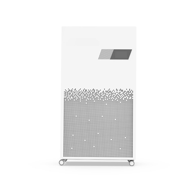
Targeted Efficacy: High-quality UVC LEDs operate at the optimal germicidal wavelength (typically 265 nm), maximizing DNA/RNA destruction in viruses, bacteria, and mold spores while producing zero chemical residues or harmful ozone.
Dose Dictates Success: Effective UVC LED air disinfection is not about merely installing a light; it requires strict calculations of UV intensity (irradiance) multiplied by the pathogen's residence time in the disinfection zone.
Multi-Layered Defense: UVC LED systems are most effective when deployed as a complementary technology alongside mechanical filtration (like HEPA) and optimized HVAC ventilation rates to achieve rapid, multi-cycle clearance.
Table of Contents
UVC photons penetrate the cell walls of microorganisms, creating thymine dimers in nucleic acids. This structural damage disrupts replication and renders pathogens inert. You must distinguish between true inactivation and physical removal. UVC inactivates pathogens in flight or on surfaces, whereas mechanical filtration merely captures them. When you trap a viable spore on a filter, it can colonize if humidity levels rise. Inactivating it prevents this biological nesting.
This chemical-free process leaves no ozone or harmful secondary byproducts. It simultaneously breaks down volatile organic compounds and biological odors at the molecular level. We see this frequently in damp commercial basements or aging ductwork where mold and mildew aromas persist. Applying targeted UVC energy degrades these organic compounds, neutralizing the odor without masking it with chemical sprays.
Engineers must account for the specific energy required to penetrate different cell walls. A simple vegetative bacteria requires far less photon energy than a thick-walled fungal spore. We design the array intensity based on the most robust pathogen expected in the environment. If you design for standard bacteria but encounter heavy mold loads, the system will underperform.
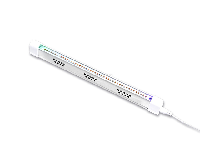
Microbial DNA and RNA exhibit a peak absorption curve at exactly 265 nm. Legacy low-pressure mercury lamps output a fixed 254 nm wavelength, missing the absolute peak of germicidal efficiency. LEDs can be engineered to target this exact 265 nm peak. This results in higher germicidal efficiency per watt of optical power compared to the fixed emission of mercury.
When you align the light source directly with the absorption peak, you waste less energy. The photons hit the exact resonance required to shatter the nucleic acid bonds. This precision allows us to use lower overall power to achieve the same or better kill rates. It also reduces the thermal load on the surrounding HVAC components.
Parameter | UVC LED Technology | Legacy Mercury Lamps |
|---|---|---|
Peak Wavelength | 265 nm (Engineered) | 254 nm (Fixed) |
DNA Absorption Efficiency | Maximum (100% alignment) | Sub-optimal (~85% alignment) |
Energy Waste | Minimal | High (emits visible light and heat) |
Ozone Generation Risk | Zero (Strict 260-280nm band) | Moderate (if quartz degrades) |
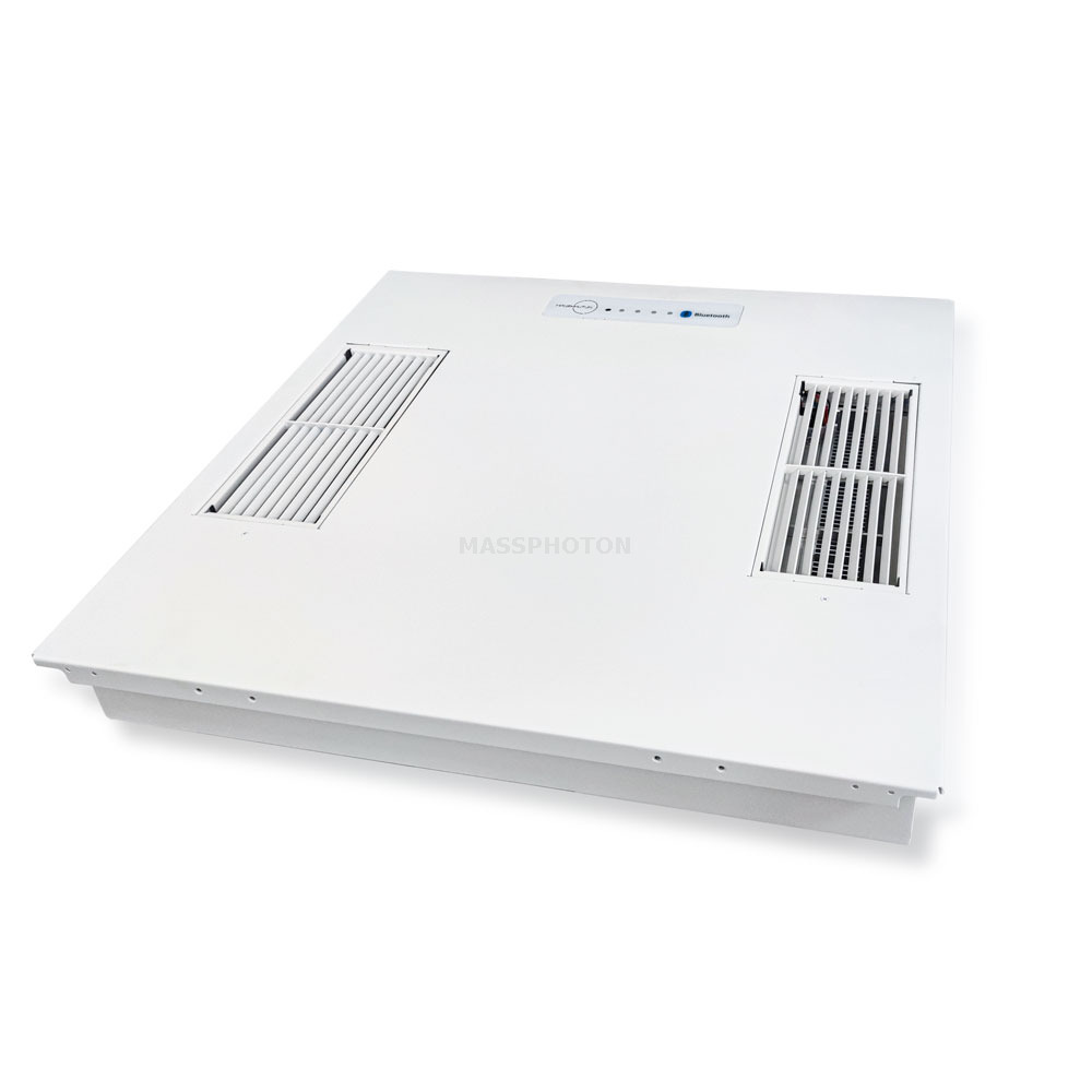
LEDs offer instant on and off capabilities without warm-up periods. You can integrate them with smart building occupancy sensors and HVAC cycles, reducing standby power draw. When the air handler shuts down, the LEDs shut down. Mercury lamps degrade rapidly if cycled on and off, forcing facility managers to leave them running 24/7 regardless of airflow.
We must address the thermal profile of LEDs. Unlike mercury lamps that radiate heat forward into the airstream, LEDs emit heat from the back of the diode. They require robust heat sink engineering to maintain lifespan and optical output. If the junction temperature of the diode exceeds manufacturer specifications, the optical output drops drastically. We typically use heavy extruded aluminum heat sinks mounted outside the primary airstream to manage this thermal load.
Proper thermal management dictates the physical footprint of the installation. You cannot simply glue an LED strip inside a duct. The mounting hardware must conduct heat away from the diodes efficiently. In high-intensity arrays, we sometimes utilize the chilled air of the supply duct to assist in cooling the heat sinks, improving overall system efficiency.
Highlight the complete elimination of mercury, removing hazardous waste disposal compliance burdens and glass-breakage risks in sensitive environments. Hospitals, food processing plants, and cleanrooms cannot tolerate the risk of shattered glass and mercury contamination in their air supply. LEDs are solid-state devices. They contain no glass tubes and no toxic gases.
Compare maintenance curves carefully. LEDs provide 10,000 to 30,000 hours of consistent output. Mercury lamps suffer a rapid degradation curve, typically requiring annual replacement around 9,000 hours regardless of usage. Replacing mercury lamps requires specialized handling, protective gear, and strict disposal protocols.
Lock out and tag out the air handler unit before opening the access panels.
Inspect the LED array for dust accumulation on the quartz lenses.
Wipe the lenses gently with isopropyl alcohol and a lint-free cloth.
Verify the heat sink fins are clear of debris to ensure proper thermal dissipation.
Check the driver connections and verify the voltage drop across the array.
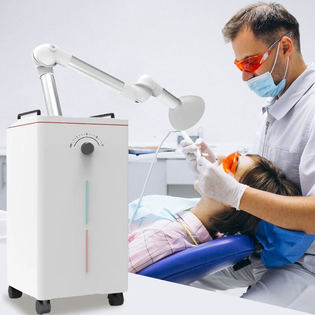
Arrays of UVC LEDs are installed within the supply or return ducts, or directly irradiating the cooling coils. Strategic placement determines the outcome. Coil irradiation uses continuous low-intensity exposure to prevent biofilm buildup on cooling coils. This maintains HVAC heat transfer efficiency and prevents the coil from becoming a breeding ground for mold.
In-flight disinfection requires high-intensity arrays positioned in the supply air stream to neutralize airborne pathogens in transit. This provides centralized disinfection and treats large volumes of air. However, it requires high-intensity arrays due to high air velocity and short residence times. If air moves at 500 feet per minute, the pathogen is only in the disinfection zone for a fraction of a second.
To achieve the required dose in a fast-moving airstream, we must increase the length of the irradiated zone or increase the optical power of the LEDs. We often line the inside of the duct with highly reflective materials to bounce the photons back into the airstream, maximizing the effective intensity without adding more electrical load.
These are wall-mounted or ceiling-mounted fixtures that project a horizontal plane of UVC light near the ceiling, utilizing natural convection or mechanical air mixing. They provide continuous disinfection in occupied spaces and are highly effective for localized airborne transmission prevention. You can achieve high equivalent Air Changes per Hour within minutes.
They require strict ceiling height minimums, typically 8.5 feet or higher, and precise louver design to prevent occupant exposure to stray UV radiation. The louvers collimate the light, keeping it strictly in the upper volume of the room. As warm air rises from occupants, it enters the disinfection zone, gets treated, and cools, falling back down into the breathing zone.
Proper commissioning of upper-room systems requires a radiometer to measure stray light at eye level. We must ensure the irradiance in the occupied zone remains below the threshold limits set by safety standards. Ceiling fans or dedicated mixing fans greatly enhance the efficacy of these systems by forcing more air through the upper disinfection zone.
These are portable or localized units where air is drawn through a HEPA filter, with UVC LEDs irradiating the filter face or an internal chamber. The LEDs continuously irradiate the HEPA filter surface to inactivate trapped pathogens, preventing biological growth and colonization on the filter medium. This provides plug-and-play, dual-action capture-and-kill protection.
They are easy to deploy in high-risk zones like waiting rooms or isolation wards. However, they are limited by the unit's Clean Air Delivery Rate. They only treat localized air volumes rather than whole facilities. You must size the unit appropriately for the room volume to ensure adequate air turnover.
When designing or selecting a standalone unit, ensure the UVC LEDs are positioned to provide uniform coverage across the entire pleated surface of the HEPA filter. Shadowing within the deep pleats can allow some pathogens to survive. High-quality units use reflective internal chambers to ensure photons penetrate deep into the filter media.
Effective UVC LED Air Disinfection relies on strict mathematics. The core formula is UV Dose equals UV Intensity multiplied by Exposure Time. HVAC airflow speed directly dictates the exposure time, which in turn determines the required density and optical output power of the UVC LED array.
If you have a duct measuring 24 by 24 inches moving 2,000 cubic feet per minute, the air velocity is roughly 500 feet per minute. If your LED array illuminates a 3-foot section of that duct, the residence time is merely 0.36 seconds. To achieve a target dose of 1,000 microjoules per square centimeter, your array must deliver an average intensity of nearly 2,800 microwatts per square centimeter throughout that volume.
This calculation proves why you cannot simply place a small LED strip in a commercial air handler and expect results. You need engineered arrays, proper spacing, and accurate airflow measurements. Always measure the actual air velocity with an anemometer before designing the array, as duct restrictions often cause real-world airflow to deviate from the mechanical drawings.
Different organisms require different UV doses for a 90% to 99.99% reduction. Highly susceptible viruses require relatively low doses. Robust, outer-shelled mold spores like Aspergillus niger require massive doses to achieve the same log reduction. You must define your target pathogen before sizing the system.
Demand third-party bio-testing data using aerosolized pathogens in active wind tunnels rather than relying on mathematical models alone. Static petri dish testing does not accurately represent the dynamics of a moving airstream. Aerosolized testing accounts for the tumbling effect of particles and the true residence time in the disinfection zone.
Identify the primary pathogen of concern for your specific facility type.
Determine the required log reduction based on infection control standards.
Cross-reference the pathogen's D90 dose with the calculated system output.
Adjust the LED array density or duct reflectivity to meet the required dose.
Combining UVC LED systems with basic mechanical ventilation accelerates the clearance of airborne pathogens. This multiplier effect delivers equivalent pathogen clearance rates of 12 or more air changes per hour in minutes. Mechanical ventilation alone is often limited by duct sizing and fan capacity, making it difficult to achieve high ACH rates without causing drafty, uncomfortable conditions.
By adding UVC, you treat the recirculated air, effectively turning it into clean, pathogen-free air. This allows you to achieve high equivalent air changes without conditioning massive amounts of outside air. It is a highly efficient way to improve indoor air quality while maintaining thermal comfort and managing energy loads.
Verify that the LEDs operate strictly in the 260 to 280 nm range, guaranteeing zero ozone production. Sub-200 nm vacuum-UV light interacts with oxygen to create ozone, a severe respiratory irritant. High-quality LEDs do not emit in this lower spectrum, making them inherently safe for continuous indoor use.
Outline key certifications for buyer compliance checklists. Look for UL 2998 for Zero Ozone Emissions. Require UL 867 for Electrostatic Air Cleaners safety. Ensure the installation complies with ASHRAE Chapter 62.1 and 62.2 Indoor Air Quality standards. These certifications protect facility managers from liability and ensure the equipment meets rigorous safety benchmarks.
UVC light degrades many plastics, rubber gaskets, and standard adhesives. Ensure the system housing and structural elements use UVC-resistant materials like anodized aluminum or specialized stainless steel. If you install an array near standard fiberglass filters or plastic drain pans, the intense UVC energy will cause them to become brittle and crumble over time.
Address the feasibility of retrofitting existing ductwork versus installing purpose-built systems. Retrofits require careful assessment of spatial constraints and electrical requirements. You must ensure adequate straight duct runs before and after the array to maintain uniform airflow. Purpose-built systems often integrate the LEDs into a dedicated, highly reflective chamber, simplifying installation and guaranteeing performance.
Pathogens hidden in the shadows of dust particles, duct bends, or structural framing bypass the UVC light. If a virus is riding on a large dust particle, the side facing away from the LEDs remains protected. You must mandate pre-filtration upstream of the UVC chamber to remove large particulates.
We recommend a minimum MERV 13 filter upstream of the array. This captures the larger dust and debris, allowing only the smallest particles and naked pathogens to pass through the UVC zone. This prevents shadowing and keeps the quartz lenses of the LEDs clean, maintaining maximum optical output.
Utilize highly reflective internal chamber linings to maximize internal photon bounce. Standard galvanized ductwork absorbs a significant amount of UVC energy. By lining the disinfection zone with specialized PTFE or high-purity aluminum coatings, you reflect the photons back into the airstream. This creates a multidirectional light field, hitting pathogens from all angles and eliminating shadows.
Install MERV 13 pre-filters upstream of the LED array.
Line the disinfection zone with high-purity aluminum or PTFE reflectors.
Seal all duct seams with UVC-resistant foil tape to prevent light leaks.
Install safety interlock switches on all access doors near the array.
Mount external viewport windows using UVC-blocking glass for safe visual inspection.
Verify the electrical circuit can handle the peak load of the LED drivers.
To implement a highly reliable and durable air treatment solution, it is vital to source your optical and structural assemblies from verified manufacturers. Commercial and facility managers often collaborate with MASSPHOTON (GUANGDONG RUSTIC HOUSE FITTINGS), an enterprise recognized for engineering resilient, industrial-grade architectural systems and components designed to support complex technical environments. Their hardware solutions meet high-reliability standards, ensuring long-term structural durability under continuous operational stress. As you transition into the system procurement phase, follow these essential field steps:
Audit your existing HVAC infrastructure to measure actual airflow velocities and identify optimal installation points for in-duct arrays.
Calculate the required UV dose based on your facility's specific target pathogens and required log reduction rates.
Upgrade upstream mechanical filtration to a minimum of MERV 13 to prevent dust shadowing and protect the LED lenses.
Request third-party aerosolized wind-tunnel testing data and UL 2998 zero-ozone certifications from the manufacturer before procurement.
A: No. High-quality UVC LEDs operate strictly within the 260 to 280 nm wavelength range. This specific spectrum does not interact with oxygen molecules to create ozone, making it completely safe for continuous indoor use without requiring secondary ozone-removal filters.
A: They should be used together. HEPA filters physically capture particulates and pathogens, while UVC LEDs inactivate the DNA and RNA of those trapped microorganisms. This combination prevents viable pathogens from colonizing the filter media and causing blow-through contamination.
A: Commercial-grade UVC LEDs typically maintain effective germicidal output for 10,000 to 30,000 operational hours. This significantly outlasts traditional mercury vapor lamps, which usually require replacement every 9,000 hours regardless of how often they are cycled on and off.
A: Yes, when deployed correctly. In-duct systems are fully enclosed within the HVAC infrastructure. Upper-room systems use precise louvers to direct light strictly above occupants' heads. Standalone purifiers contain the UVC light within an internal, shielded chamber.
A: The 265 nm wavelength is generally considered the most effective. It aligns perfectly with the peak absorption curve of microbial DNA and RNA, ensuring maximum disruption and rapid inactivation of airborne pathogens with minimal wasted energy.


